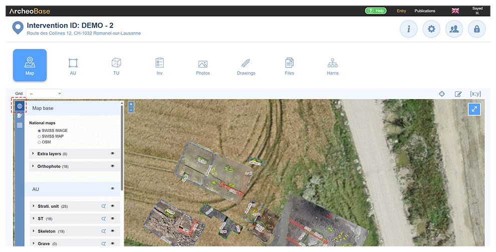
The map menu, listing all elements with coordinates, can be displayed by clicking on the icon  .
Assignment of topo points
The map menu offers an overview of the site elements with Topo points. It also shows the list of imported Topo points not directly linked to a form, photo or drawing. For example, Topo points defining the excavation perimeter.
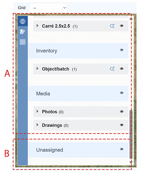
| A: Assigned topo points | List of site elements (Forms, Photos, Drawings) with Topo points. |
| B: Unassigned topo points |
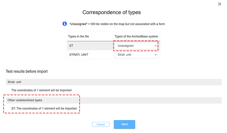
Unassignments are generated when importing a coordinate file where the form types in the file don't exist in ArcheoBase. In the example below, the file to import includes Topo points defining the site perimeter. However, no Excavation perimeter form was created in ArcheoBase because it's not relevant. Still, displaying those Topo points on the map is useful. Therefore, import is done by selecting Unassigned in the matching window.
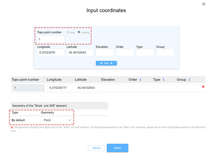
The Topo points are then imported into ArcheoBase and added at the bottom of the map menu under Unassigned. If needed, Unassigned topo points can be linked later when forms are created in ArcheoBase, through the Coordinates tab of each form. Simply select their Topo point number and desired geometry type.
|
Geometry visualization
The map menu allows visualizing geometries.
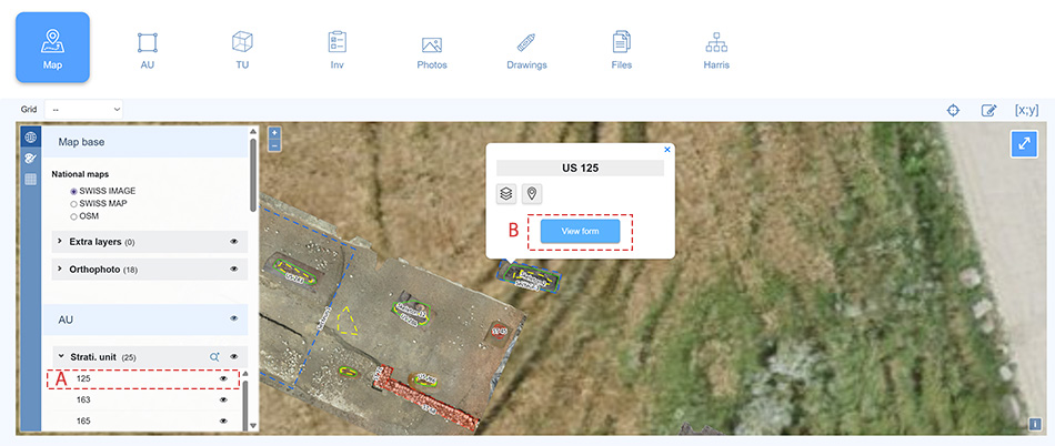
- Clicking a form line centers the map on its geometry (A).
- Clicking View form (B) opens the form.
- The icon
 opens the Advanced search menu
- The icon
 toggles visibility of geometries.
Advanced search
The display of items on the map can be filtered via the Advanced search menu, by clicking the icon next to the form type in the map menu. The menu allows forms with specific properties and values (A) and/or specific “Associated with” relationships (B) to be displayed on the map.
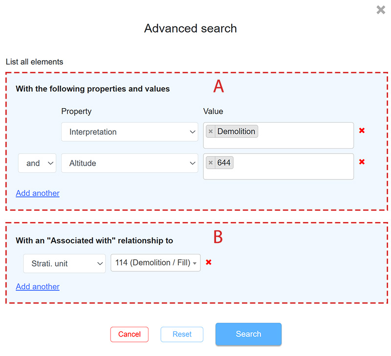
A: Filter by properties and values
Displays only the forms that have a specific property and value, or a combination of properties and values. The properties and values correspond to those defined for the form type.
B: Filter by “Associated with” relationships
Displays only the forms that have a specific “Associated with” relationship, or a combination of “Associated with” relationships.
The map display is filtered using the Search button. The Reset button clears all search parameters.
Map configuration
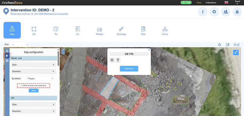
The style and representation of geometries can be configured via the Map Configuration Menu, by clicking the icon  in the left vertical menu. Each form type has a default style and geometry type.
A: Style
Line, thickness, fill, color, and transparency can be customized. These settings apply to all users and interventions.
B: Default geometry
Each form type has a default geometry. For example, all Topo points of a form may be shown as circles of a given diameter, such as in a hypothetical Posthole form. Each point would be interpreted as a circle.
Conversely, a US form with default polygon geometry would link its topo points to form one polygon.
Default geometry doesn’t prevent setting a custom geometry per form through the Coordinates menu. The following example shows this:
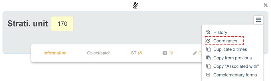
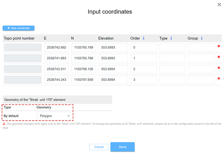
If needed, custom configurations can later be removed by selecting Delete individually made configurations from the Map Configuration Menu.
The Topo points forming each geometry can be viewed by clicking the geometry on the map and the icon 
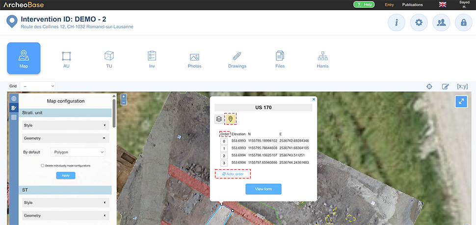
- The Order of the Topo points can be changed by modifying their numbering.
- The Auto order button reorganizes the Topo points into likely combinations, generating polygons without intersecting lines.
If topo points were taken on-site in a specific order (e.g., clockwise), the geometry can always be auto-generated from that order.
However, reordering topo points is often needed in trench work, where points may be recorded from alternating sides. The initial order may not form a coherent shape, hence the need to reorder manually or with Auto order. This works best with a limited number of points, as valid combinations increase exponentially.
Geometries added to the map behave like stacked layers, with newer ones on top. The stacking order can be changed by editing the Layer level number. Default is 100.
This is useful, for example, if a Sector was drawn after US. Clicking the US may select the Sector instead, as it sits above. Change the Sector’s layer to 99 to place it below.
Clicking the geometry on the map and the icon  allows editing the Layer level value.
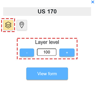
Tip: if two geometries overlap, a mouse click will select the top one. Clicking again selects the one underneath.
Base maps can either be default backgrounds included in ArcheoBase (A), or custom maps added by the user (B).
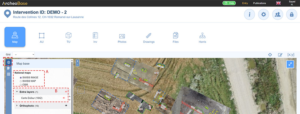
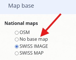
A: Default base maps
Default base maps may vary depending on the country where ArcheoBase is deployed.
The base map can also be disabled to exclusively display geometries and orthophotos.
B: Custom base maps
Additional specific base maps tailored to an organization's needs can be added.
- If so, please contact the support team
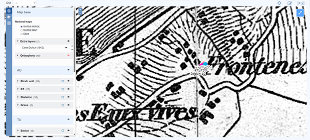
Here is an example of a custom background based on a historic map: